Wisdom
-
-
-
-
EMC Test System For Civil Products
-
- Electrostatic Discharge Immunity
- Radiated, radio-frequency,electromagnetic field immunity
- Electrical Fast Transient Burst Immunity
- Surge immunity
- Immunity To Conducted Disturbance Induced by Radio Frequency Field
- Power Frequency Magnetic Field Immunity
- Voltage dips, short interruptions and voltage variations immunity
- Harmonics and interharmonics including mains signalling at AC power port, low frequency immunity
- Voltage Fluctuation Immunity Test
- Common mode disturbances in the frequency range 0 Hz to 150 kHz Immunity
- Ripple on DC input power port immunity
- Three-phase Voltage Unbalance Immunity Test
- Power Frequency Variation Immunity Test
- Oscillatory Wave Immunity Test
- Damped Oscillatory Magnetic Field Immunity Test
- Differential mode disturbances immunity test
- DC power input port voltage dip, short interruption and voltage variations test
-
Automotive Electronic EMC Test System
-
- Electrostatic Discharge Immunity
- Electrical Transient Conducted Immunity
- Immunity Test To Narrowband Radiated Electromagnetic Energy-Anechoic Chamber Method
- Immunity Test To Narrowband Radiated Electromagnetic Energy-Transverse Wave (TEM) Cell Method
- Immunity Test To Narrowband Radiated Electromagnetic Energy-large Current injection (BCI) method
- Immunity Test To Narrowband Radiated Electromagnetic Energy-Stripline Method
- Immunity Test To Narrowband Radiated Electromagnetic Energy-direct Injection Of Radio Frequency (RF) Power
- Immunity Test To Narrowband Radiated Electromagnetic Energy-Magnetic Field Immunity Method
- Immunity Test To Narrowband Radiated Electromagnetic Energy-Portable Transmitter Simulation Method
- Immunity Test To Narrowband Radiated Electromagnetic Energy-Conduction Immunity Method For Extended Audio Range
- High Voltage Electrical Performance ISO 21498-2 Test System
- High Voltage Transient Conducted Immunity (ISO 7637-4)
-
-
- CE101(25Hz ~ 10kHz power line conduction emission)
- CE102(10kHz ~ 10MHz power line conduction emission)
- CE106(10kHz ~ 40GHz antenna port conducted emission)
- CE107 (Power Line Spike (Time Domain) Conducted Emission)
- RE101(25Hz ~ 100kHz magnetic field radiation emission)
- RE102(10kHz ~ 18GHz electric field radiation emission)
- RE103(10kHz ~ 40GHz antenna harmonic and spurious output radiated emission)
-
- CS101(25Hz ~ 150kHz power line conduction sensitivity)
- CS102(25Hz ~ 50kHz ground wire conduction sensitivity)
- CS103(15kHz ~ 10GHz Antenna Port Intermodulation Conducted Sensitivity)
- CS104(25Hz ~ 20GHz antenna port unwanted signal suppression conduction sensitivity)
- CS105(25Hz ~ 20GHz antenna port intermodulation conduction sensitivity)
- CS106 (Power Line Spike Signal Conduction Sensitivity)
- CS109(50Hz ~ 100kHz shell current conduction sensitivity)
- CS112 (Electrostatic Discharge Sensitivity)
- CS114(4kHz ~ 400MHz cable bundle injection conduction sensitivity)
- CS115 (Conduction sensitivity of cable bundle injection pulse excitation)
- CS116(10kHz to 100MHz Cable and Power Line Damped Sinusoidal Transient Conduction Sensitivity)
- RS101(25Hz ~ 100kHz magnetic field radiation sensitivity)
- RS103(10kHz ~ 40GHz electric field radiation sensitivity)
- RS105 (Transient Electromagnetic Field Radiated Susceptibility)
-
-
-
-
-
-
-
-
-
-
EMC Test System For Civil Products
-
- Electrostatic Discharge Immunity
- Radiated, radio-frequency,electromagnetic field immunity
- Electrical Fast Transient Burst Immunity
- Surge immunity
- Immunity To Conducted Disturbance Induced by Radio Frequency Field
- Power Frequency Magnetic Field Immunity
- Voltage dips, short interruptions and voltage variations immunity
- Harmonics and interharmonics including mains signalling at AC power port, low frequency immunity
- Voltage Fluctuation Immunity Test
- Common mode disturbances in the frequency range 0 Hz to 150 kHz Immunity
- Ripple on DC input power port immunity
- Three-phase Voltage Unbalance Immunity Test
- Power Frequency Variation Immunity Test
- Oscillatory Wave Immunity Test
- Damped Oscillatory Magnetic Field Immunity Test
- Differential mode disturbances immunity test
- DC power input port voltage dip, short interruption and voltage variations test
-
Automotive Electronic EMC Test System
-
- Electrostatic Discharge Immunity
- Electrical Transient Conducted Immunity
- Immunity Test To Narrowband Radiated Electromagnetic Energy-Anechoic Chamber Method
- Immunity Test To Narrowband Radiated Electromagnetic Energy-Transverse Wave (TEM) Cell Method
- Immunity Test To Narrowband Radiated Electromagnetic Energy-large Current injection (BCI) method
- Immunity Test To Narrowband Radiated Electromagnetic Energy-Stripline Method
- Immunity Test To Narrowband Radiated Electromagnetic Energy-direct Injection Of Radio Frequency (RF) Power
- Immunity Test To Narrowband Radiated Electromagnetic Energy-Magnetic Field Immunity Method
- Immunity Test To Narrowband Radiated Electromagnetic Energy-Portable Transmitter Simulation Method
- Immunity Test To Narrowband Radiated Electromagnetic Energy-Conduction Immunity Method For Extended Audio Range
- High Voltage Electrical Performance ISO 21498-2 Test System
- High Voltage Transient Conducted Immunity (ISO 7637-4)
-
-
- CE101(25Hz ~ 10kHz power line conduction emission)
- CE102(10kHz ~ 10MHz power line conduction emission)
- CE106(10kHz ~ 40GHz antenna port conducted emission)
- CE107 (Power Line Spike (Time Domain) Conducted Emission)
- RE101(25Hz ~ 100kHz magnetic field radiation emission)
- RE102(10kHz ~ 18GHz electric field radiation emission)
- RE103(10kHz ~ 40GHz antenna harmonic and spurious output radiated emission)
-
- CS101(25Hz ~ 150kHz power line conduction sensitivity)
- CS102(25Hz ~ 50kHz ground wire conduction sensitivity)
- CS103(15kHz ~ 10GHz Antenna Port Intermodulation Conducted Sensitivity)
- CS104(25Hz ~ 20GHz antenna port unwanted signal suppression conduction sensitivity)
- CS105(25Hz ~ 20GHz antenna port intermodulation conduction sensitivity)
- CS106 (Power Line Spike Signal Conduction Sensitivity)
- CS109(50Hz ~ 100kHz shell current conduction sensitivity)
- CS112 (Electrostatic Discharge Sensitivity)
- CS114(4kHz ~ 400MHz cable bundle injection conduction sensitivity)
- CS115 (Conduction sensitivity of cable bundle injection pulse excitation)
- CS116(10kHz to 100MHz Cable and Power Line Damped Sinusoidal Transient Conduction Sensitivity)
- RS101(25Hz ~ 100kHz magnetic field radiation sensitivity)
- RS103(10kHz ~ 40GHz electric field radiation sensitivity)
- RS105 (Transient Electromagnetic Field Radiated Susceptibility)
-
-
-
-
-
-
Product
EMC Testing Solution Provider
ESA1 set electromagnetic interference development system
Brand:
LANGER

- Product Description
- Main features
- Technical parameters
-
- Commodity name: ESA1 set electromagnetic interference development system
- Commodity ID: 1064680357996679168
- 品牌11: LANGER
- 描述: The ESA 1 Electromagnetic Interference Development System is an EMC tool for measuring interference from components and equipment.
- 品牌: LANGER
The ESA 1 Electromagnetic Interference Development System is an EMC tool for measuring the interference of components and equipment. For fast and comprehensive interference removal, the system includes a set of CS-ESA software customized according to the developer's work. This set of ESA 1 is designed for the developer's workplace. The interference emission measurements made with the ESA 1 during development are directly proportional to the far-field measurements or measurements with artificial mains networks. Use the tools in the ESA 1 system to locate the interference source and find the action path of the interference coupling. In this way, a reasonable EMC solution can be found and its dimensions can be determined. The improvement obtained with the ESA 1 is directly proportional to the far-field measurement results.
The traditional EMI test adopts the far-field test method, and uses the electromagnetic compatibility test antenna to receive the radiation generated by the object under test (EUT). This test method must have a relatively open site and relatively expensive equipment, and it needs to be tested after the object under test is assembled into a system. Due to the existence of a large number of radio and TV station signals in the working environment, these signals are "background noise" for EMI testing. To conduct accurate testing, it must be carried out in a dark room. If testing in a normal working environment, it is necessary to take Advanced background noise filtering function [such as CASSPER virtual darkroom EMI test system].
ESA 1 electromagnetic interference development system is a set of electromagnetic interference testing and debugging system on the experimental table. It is suitable for testing the electromagnetic interference generated by PCB during the product development stage, evaluating design modifications, improving work efficiency and speeding up product development time.
ESA 1 electromagnetic interference development system is based on the following principles for EMI testing and debugging:
In most cases, electromagnetic interference is not caused by a component or a signal line, but is formed by the coupling of the entire metal system of the EUT through a magnetic field or an electric field. This metal system includes the PCB and all cables and chassis connected to it. The metallic system as a whole acts as a source of interference for EMI and acts as an antenna for emitting EMI. ESA 1 tests the source of electromagnetic interference, that is, the electromagnetic interference current on the metal object, such as the current from the PCB to the cable.
Measurements are performed on a conductive substrate, which reduces the influence of measuring devices, cable locations and ambient electromagnetic interference. Couple the interference current to the substrate through the capacitive coupling device, and then measure the current ierr on the current loop formed by the capacitive device and the substrate. This measurement method has good repeatability, so that the design modification can be correctly evaluated effectiveness.
Typical EMI problems are generally due to the following two reasons:
1. Common mode interference on the cable
Generally, the power supply filtering of one or several IC chips on the PCB is not well considered, causing the ΔI noise on the power supply to be introduced into the connector and cable through the power supply or ground network, and this electromagnetic interference becomes a common mode on the cable. interference. There is also a possibility that the differential mode current loops through the connector, so that the differential mode EMI will become common mode EMI.
For EMI testing, the impact of common-mode interference is 100 to 1000 times greater than differential-mode interference. That is to say, the interference caused by 10mA differential mode current may be the same as the interference caused by 0.1mA common mode current.
ESA 1 can be used to easily measure the electromagnetic interference current parasitic on the power supply or ground network, and can also measure the common mode current and differential mode current respectively.
2. Large area differential mode current loop
Excessively long signal lines and improper current loops will generate a large area of differential mode current. Far-field test results are proportional to the current loop area. In terms of measuring the area of the current loop, ESA 1 must use various near-field probes to perform detailed measurements [if the EMSCAN electromagnetic interference scanning system is used, the efficiency will be higher]. But ESA 1 can easily measure the interference current intensity on the current loop, and correctly judge whether the interference current is common mode or differential mode. It has very important guiding significance for the elimination of EMI problems.
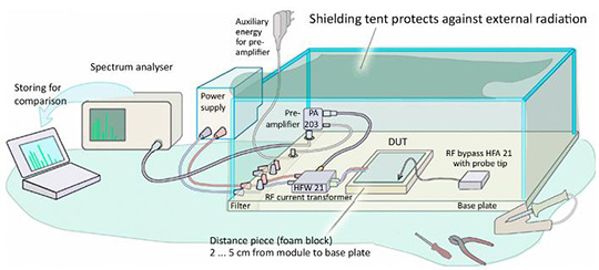
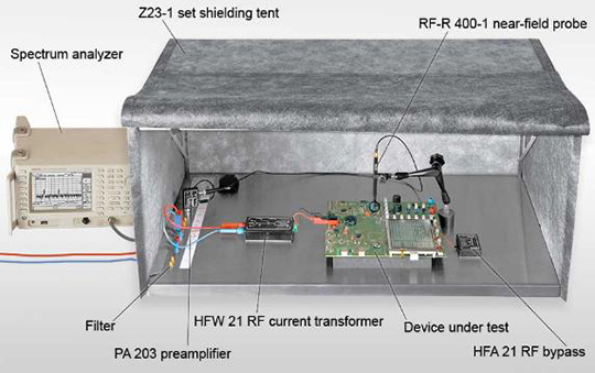
ESA 1 contains the following accessories:
CS-ESA set, ESA chip scanning software
HFW 21, RF current converter
HFA 21, RF leads
Z23-1 set, shielding canopy (900x500x400 mm)
PA 203 BNC, preamplifier (100KHz~3GHz)
RF-B 0.3-3, mini magnetic field probe (30MHz~3GHz)
RF-B 3-2, magnetic field probe (30MHz~3GHz)
RF-E 02, electric field probe (30MHz~3GHz)
RF-E 05, electric field probe (30MHz~3GHz)
RF-E 10, electric field probe (30MHz~3GHz)
RF-R 0.3-3, mini magnetic field probe (30MHz~3GHz)
RF-R 3-2, magnetic field probe (30MHz~3GHz)
RF-R 50-1, magnetic field probe (30MHz~3GHz)
RF-R 400-1, magnetic field probe (30MHz~3GHz)
RF-U 2.5-2, magnetic field probe (30MHz~3GHz)
RF-U 5-2, magnetic field probe (30MHz~3GHz)
ESA1 acc
ESA1 case
ESA1 m, Operating Instructions
-
Specific indicators:
HFW 21 RF Current Converter
Frequency Range
100 kHz~1 GHz
electric current
10 A
Compressive strength
50 V
Dimensions (LxWxH)
(135 x 32 x 28) mm
HFA 21 RF leads
capacitance
10 pF~100 nF
Compressive strength
50 V
Shielding canopy (900x500x400 mm)
Shielding attenuation
45 dB~50 dB / 30 MHz~1GHz
Dimensions (LxWxH)
(900 x 500 x 400) mm
weight
12 kg
Near Field Probe Set
Frequency Range
30 MHz~3 GHz
ESA chip scanning software
operating system
Windows XP/Vista/7 (latest service packs)
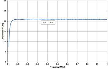
PA 203 preamplifier
Frequency Range
100 kHz~3 GHz
enlarge
20 dB
voltage
12 V DC
current input
50 mA
Maximum input power
+13 dBm
Frequency characteristics (details)