
Wisdom
-
-
-
-
EMC Test System For Civil Products
-
- Electrostatic Discharge Immunity
- Radiated, radio-frequency,electromagnetic field immunity
- Electrical Fast Transient Burst Immunity
- Surge immunity
- Immunity To Conducted Disturbance Induced by Radio Frequency Field
- Power Frequency Magnetic Field Immunity
- Voltage dips, short interruptions and voltage variations immunity
- Harmonics and interharmonics including mains signalling at AC power port, low frequency immunity
- Voltage Fluctuation Immunity Test
- Common mode disturbances in the frequency range 0 Hz to 150 kHz Immunity
- Ripple on DC input power port immunity
- Three-phase Voltage Unbalance Immunity Test
- Power Frequency Variation Immunity Test
- Oscillatory Wave Immunity Test
- Damped Oscillatory Magnetic Field Immunity Test
- Differential mode disturbances immunity test
- DC power input port voltage dip, short interruption and voltage variations test
-
Automotive Electronic EMC Test System
-
- Electrostatic Discharge Immunity
- Electrical Transient Conducted Immunity
- Immunity Test To Narrowband Radiated Electromagnetic Energy-Anechoic Chamber Method
- Immunity Test To Narrowband Radiated Electromagnetic Energy-Transverse Wave (TEM) Cell Method
- Immunity Test To Narrowband Radiated Electromagnetic Energy-large Current injection (BCI) method
- Immunity Test To Narrowband Radiated Electromagnetic Energy-Stripline Method
- Immunity Test To Narrowband Radiated Electromagnetic Energy-direct Injection Of Radio Frequency (RF) Power
- Immunity Test To Narrowband Radiated Electromagnetic Energy-Magnetic Field Immunity Method
- Immunity Test To Narrowband Radiated Electromagnetic Energy-Portable Transmitter Simulation Method
- Immunity Test To Narrowband Radiated Electromagnetic Energy-Conduction Immunity Method For Extended Audio Range
- High Voltage Electrical Performance ISO 21498-2 Test System
- High Voltage Transient Conducted Immunity (ISO 7637-4)
-
-
- CE101(25Hz ~ 10kHz power line conduction emission)
- CE102(10kHz ~ 10MHz power line conduction emission)
- CE106(10kHz ~ 40GHz antenna port conducted emission)
- CE107 (Power Line Spike (Time Domain) Conducted Emission)
- RE101(25Hz ~ 100kHz magnetic field radiation emission)
- RE102(10kHz ~ 18GHz electric field radiation emission)
- RE103(10kHz ~ 40GHz antenna harmonic and spurious output radiated emission)
-
- CS101(25Hz ~ 150kHz power line conduction sensitivity)
- CS102(25Hz ~ 50kHz ground wire conduction sensitivity)
- CS103(15kHz ~ 10GHz Antenna Port Intermodulation Conducted Sensitivity)
- CS104(25Hz ~ 20GHz antenna port unwanted signal suppression conduction sensitivity)
- CS105(25Hz ~ 20GHz antenna port intermodulation conduction sensitivity)
- CS106 (Power Line Spike Signal Conduction Sensitivity)
- CS109(50Hz ~ 100kHz shell current conduction sensitivity)
- CS112 (Electrostatic Discharge Sensitivity)
- CS114(4kHz ~ 400MHz cable bundle injection conduction sensitivity)
- CS115 (Conduction sensitivity of cable bundle injection pulse excitation)
- CS116(10kHz to 100MHz Cable and Power Line Damped Sinusoidal Transient Conduction Sensitivity)
- RS101(25Hz ~ 100kHz magnetic field radiation sensitivity)
- RS103(10kHz ~ 40GHz electric field radiation sensitivity)
- RS105 (Transient Electromagnetic Field Radiated Susceptibility)
-
-
-
-
-
-
-
-
-
-
EMC Test System For Civil Products
-
- Electrostatic Discharge Immunity
- Radiated, radio-frequency,electromagnetic field immunity
- Electrical Fast Transient Burst Immunity
- Surge immunity
- Immunity To Conducted Disturbance Induced by Radio Frequency Field
- Power Frequency Magnetic Field Immunity
- Voltage dips, short interruptions and voltage variations immunity
- Harmonics and interharmonics including mains signalling at AC power port, low frequency immunity
- Voltage Fluctuation Immunity Test
- Common mode disturbances in the frequency range 0 Hz to 150 kHz Immunity
- Ripple on DC input power port immunity
- Three-phase Voltage Unbalance Immunity Test
- Power Frequency Variation Immunity Test
- Oscillatory Wave Immunity Test
- Damped Oscillatory Magnetic Field Immunity Test
- Differential mode disturbances immunity test
- DC power input port voltage dip, short interruption and voltage variations test
-
Automotive Electronic EMC Test System
-
- Electrostatic Discharge Immunity
- Electrical Transient Conducted Immunity
- Immunity Test To Narrowband Radiated Electromagnetic Energy-Anechoic Chamber Method
- Immunity Test To Narrowband Radiated Electromagnetic Energy-Transverse Wave (TEM) Cell Method
- Immunity Test To Narrowband Radiated Electromagnetic Energy-large Current injection (BCI) method
- Immunity Test To Narrowband Radiated Electromagnetic Energy-Stripline Method
- Immunity Test To Narrowband Radiated Electromagnetic Energy-direct Injection Of Radio Frequency (RF) Power
- Immunity Test To Narrowband Radiated Electromagnetic Energy-Magnetic Field Immunity Method
- Immunity Test To Narrowband Radiated Electromagnetic Energy-Portable Transmitter Simulation Method
- Immunity Test To Narrowband Radiated Electromagnetic Energy-Conduction Immunity Method For Extended Audio Range
- High Voltage Electrical Performance ISO 21498-2 Test System
- High Voltage Transient Conducted Immunity (ISO 7637-4)
-
-
- CE101(25Hz ~ 10kHz power line conduction emission)
- CE102(10kHz ~ 10MHz power line conduction emission)
- CE106(10kHz ~ 40GHz antenna port conducted emission)
- CE107 (Power Line Spike (Time Domain) Conducted Emission)
- RE101(25Hz ~ 100kHz magnetic field radiation emission)
- RE102(10kHz ~ 18GHz electric field radiation emission)
- RE103(10kHz ~ 40GHz antenna harmonic and spurious output radiated emission)
-
- CS101(25Hz ~ 150kHz power line conduction sensitivity)
- CS102(25Hz ~ 50kHz ground wire conduction sensitivity)
- CS103(15kHz ~ 10GHz Antenna Port Intermodulation Conducted Sensitivity)
- CS104(25Hz ~ 20GHz antenna port unwanted signal suppression conduction sensitivity)
- CS105(25Hz ~ 20GHz antenna port intermodulation conduction sensitivity)
- CS106 (Power Line Spike Signal Conduction Sensitivity)
- CS109(50Hz ~ 100kHz shell current conduction sensitivity)
- CS112 (Electrostatic Discharge Sensitivity)
- CS114(4kHz ~ 400MHz cable bundle injection conduction sensitivity)
- CS115 (Conduction sensitivity of cable bundle injection pulse excitation)
- CS116(10kHz to 100MHz Cable and Power Line Damped Sinusoidal Transient Conduction Sensitivity)
- RS101(25Hz ~ 100kHz magnetic field radiation sensitivity)
- RS103(10kHz ~ 40GHz electric field radiation sensitivity)
- RS105 (Transient Electromagnetic Field Radiated Susceptibility)
-
-
-
-
-
-
Product
EMC Testing Solution Provider
CTR2/CTR2-AD Static Discharge calibration target and adapter
Brand:
EM TEST

- Product Description
- Main features
- Technical parameters
-
- Commodity name: CTR2/CTR2-AD Static Discharge calibration target and adapter
- Commodity ID: 1064626512956379136
- 品牌11: EMTEST
- 行业: 民用
- 描述: The CTR 2 coaxial current target is used in accordance with IEC 61000-4-2 ed. 2 standard requirements for monitoring electrostatic discharge.
- 品牌: EM TEST
The CTR 2 coaxial current target is used for monitoring electrostatic discharge according to the requirements of the IEC 61000-4-2 ed.2 standard. As an option for the EM TEST electrostatic discharge simulator dito or ESD 30N, the CTR 2 can be used for measurements up to 30kV. EM TEST also provides additionally configured attenuators to match the output signal to the input of the oscilloscope.
-
main feature:
Current targets according to EN/IEC 61000-4-2
2Ohm impedance +/- 5%
Test voltage up to 30kV
+/-0.5dB insertion loss up to 1GHz
+/-1.2dB Insertion Loss up to 4GHz
Including 20dB attenuator and 1m cable RG400
Option - Additional configured attenuators
Option - 50ohm Conical Adapter Cable CTR 2-AD
Standards compliant:
EN 61000-4-2
IEC 61000-4-2
ISO 10605
Calibration/Calibration:
Calibration Setup for CTR 2 Electrostatic Target
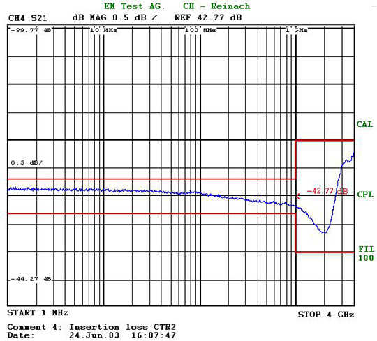
The current target CTR 2 has been verified to meet the standard requirements with an insertion loss of +/-0.5dB up to 1GHz and +/-1.2dB up to 4GHz. In addition to current monitoring, the CTR 2 has a Huber+Suhner 2W/20dB attenuator, a 1m long Huber+Suhner coaxial cable with RG400 connectors.
The "TAC" link consisting of the target, attenuator A and cable C is calibrated in this setup. Attenuators B and C are optional.

Insertion loss
S21 Measuring CTR 2 electrostatic target
This graph shows the insertion loss characteristics for a typical "TAC" chain setup.
CTR 2-AD 50 ohm cone adapter cord:
50 ohm adapter cable for calibrating CTR 2 electrostatic targets
The 50ohm tapered adapter cord connects the 50Ohm cable to the input of the CTR 2 electrostatic target. The diameter of one end of the adapter cord is equal to that of a 50Ohm coaxial cable and expands geometrically to the diameter of an electrostatic target.
If the impedance of the electrostatic target calculated from the diameter ratio d/D (refer to IEC/EN 61000-4-2 standard figure 2) is not equal to 50Ohm, then correspondingly, the outer diameter of the inner conductor of the electrostatic target adapter line should be equal to the current The diameter of the electrode built into the target.
The calculation of impedance takes into account the permittivity (dielectric constant) of the filler material (usually air) of the tapered adapter wire. The adapter wire for the electrostatic target should have an impedance of 50ohm +/- 2% from DC to 4GHz. The reflection coefficient of two face-to-face electrostatic target adapter lines should be better than 30dB when the frequency reaches 1GHz, and should be better than 20dB when the frequency reaches 4GHz; and, under the same configuration, the insertion loss should be less than 0.3dB.

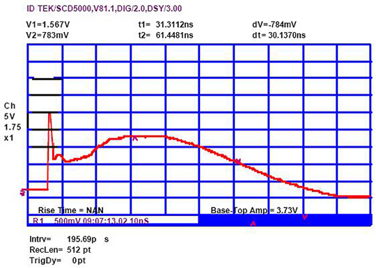
Electrostatic discharge waveform verification:
EM TEST recommends the following equipment in compliance with the requirements of the EN/IEC 61000-4-2 standard:
- Oscilloscope with at least 2GHz bandwidth
- Faraday cage
- EM TEST CTR 2 electrostatic target
Correct waveforms can only be captured with correct oscilloscope settings. Proper setup requires measuring pulses at +/-2kV, +/-4kV, +/-6kV and +/-8kV respectively, the following four parameters are measured at each voltage level:
- initial peak current
- Rise time from 10% to 90% of initial peak current value
- Current value at 30ns
- Current value at 60ns
It is recommended to set the time domain to 1ns/Div for the initial peak and rise time measurements and 10ns/Div for the current measurements at 30ns and 60ns.
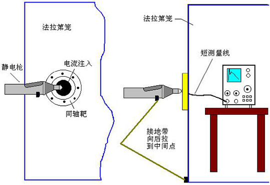
Measurement setup:
Pulse verification setup using a shielded room
This diagram shows the correct arrangement of the measuring equipment, the CTR 2 electrostatic target and the ESD simulator to be verified. As you can see from the picture, the ground return cable needs to be pulled back from the midpoint to form a loop. this point is very important. Since ground loop cables have the potential to significantly affect ESD pulses, especially when tested at the 30ns and 60ns points, if this is neglected the pulse characteristics will be affected by the range of oscillations.
How to calculate the ratio:
Relationship between peak current and measured peak voltage
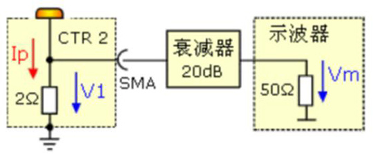
Substituting impedance and attenuation into the following equations yields the correct ratio:
Ip = 5 x Vm
in:
Vm is the voltage signal measured by the oscilloscope
V1 is the voltage measured through the CTR 2 electrostatic target
Ip is the discharge current
therefore:
V1 = 20dB x Vm = 2ohm x Ip
Ip = 20dB x Vm/2ohm
For example: 7.5A discharge current can cause the oscilloscope to display a voltage reading of 1.5V
-
Specific indicators:
Technical data
Measuring resistance
2ohm ±5%
design standards
Conforms to IEC 61000-4-2 Standard Ed.2: 2008
Install
The electrostatic calibration target should be placed on the wall of the shielded room, or installed on a metal plate with a size not less than 1.2mx 1.2m.
output
Coaxial SMA connector
Attenuator
Depending on the input of the oscilloscope, connect the attenuator to the output of CTR 2.
Insertion loss
+/-0.5dB up to 1GHz
+/-1.2dB up to 4GHz
Insertion loss must be measured with the "TAC" (calibration target-attenuator-cable) link setup, not just the calibration target.Electrostatic discharge test voltage
±30kV
size
70mm (diameter) x 30mm
weight
about 400g
option
CTR 2-AD
50ohm adapter cable for verification of CTR 2; 50ohm ±2% up to 4GHz according to EN/IEC 61000-4-2