
Wisdom
-
-
-
-
EMC Test System For Civil Products
-
- Electrostatic Discharge Immunity
- Radiated, radio-frequency,electromagnetic field immunity
- Electrical Fast Transient Burst Immunity
- Surge immunity
- Immunity To Conducted Disturbance Induced by Radio Frequency Field
- Power Frequency Magnetic Field Immunity
- Voltage dips, short interruptions and voltage variations immunity
- Harmonics and interharmonics including mains signalling at AC power port, low frequency immunity
- Voltage Fluctuation Immunity Test
- Common mode disturbances in the frequency range 0 Hz to 150 kHz Immunity
- Ripple on DC input power port immunity
- Three-phase Voltage Unbalance Immunity Test
- Power Frequency Variation Immunity Test
- Oscillatory Wave Immunity Test
- Damped Oscillatory Magnetic Field Immunity Test
- Differential mode disturbances immunity test
- DC power input port voltage dip, short interruption and voltage variations test
-
Automotive Electronic EMC Test System
-
- Electrostatic Discharge Immunity
- Electrical Transient Conducted Immunity
- Immunity Test To Narrowband Radiated Electromagnetic Energy-Anechoic Chamber Method
- Immunity Test To Narrowband Radiated Electromagnetic Energy-Transverse Wave (TEM) Cell Method
- Immunity Test To Narrowband Radiated Electromagnetic Energy-large Current injection (BCI) method
- Immunity Test To Narrowband Radiated Electromagnetic Energy-Stripline Method
- Immunity Test To Narrowband Radiated Electromagnetic Energy-direct Injection Of Radio Frequency (RF) Power
- Immunity Test To Narrowband Radiated Electromagnetic Energy-Magnetic Field Immunity Method
- Immunity Test To Narrowband Radiated Electromagnetic Energy-Portable Transmitter Simulation Method
- Immunity Test To Narrowband Radiated Electromagnetic Energy-Conduction Immunity Method For Extended Audio Range
- High Voltage Electrical Performance ISO 21498-2 Test System
- High Voltage Transient Conducted Immunity (ISO 7637-4)
-
-
- CE101(25Hz ~ 10kHz power line conduction emission)
- CE102(10kHz ~ 10MHz power line conduction emission)
- CE106(10kHz ~ 40GHz antenna port conducted emission)
- CE107 (Power Line Spike (Time Domain) Conducted Emission)
- RE101(25Hz ~ 100kHz magnetic field radiation emission)
- RE102(10kHz ~ 18GHz electric field radiation emission)
- RE103(10kHz ~ 40GHz antenna harmonic and spurious output radiated emission)
-
- CS101(25Hz ~ 150kHz power line conduction sensitivity)
- CS102(25Hz ~ 50kHz ground wire conduction sensitivity)
- CS103(15kHz ~ 10GHz Antenna Port Intermodulation Conducted Sensitivity)
- CS104(25Hz ~ 20GHz antenna port unwanted signal suppression conduction sensitivity)
- CS105(25Hz ~ 20GHz antenna port intermodulation conduction sensitivity)
- CS106 (Power Line Spike Signal Conduction Sensitivity)
- CS109(50Hz ~ 100kHz shell current conduction sensitivity)
- CS112 (Electrostatic Discharge Sensitivity)
- CS114(4kHz ~ 400MHz cable bundle injection conduction sensitivity)
- CS115 (Conduction sensitivity of cable bundle injection pulse excitation)
- CS116(10kHz to 100MHz Cable and Power Line Damped Sinusoidal Transient Conduction Sensitivity)
- RS101(25Hz ~ 100kHz magnetic field radiation sensitivity)
- RS103(10kHz ~ 40GHz electric field radiation sensitivity)
- RS105 (Transient Electromagnetic Field Radiated Susceptibility)
-
-
-
-
-
-
-
-
-
-
EMC Test System For Civil Products
-
- Electrostatic Discharge Immunity
- Radiated, radio-frequency,electromagnetic field immunity
- Electrical Fast Transient Burst Immunity
- Surge immunity
- Immunity To Conducted Disturbance Induced by Radio Frequency Field
- Power Frequency Magnetic Field Immunity
- Voltage dips, short interruptions and voltage variations immunity
- Harmonics and interharmonics including mains signalling at AC power port, low frequency immunity
- Voltage Fluctuation Immunity Test
- Common mode disturbances in the frequency range 0 Hz to 150 kHz Immunity
- Ripple on DC input power port immunity
- Three-phase Voltage Unbalance Immunity Test
- Power Frequency Variation Immunity Test
- Oscillatory Wave Immunity Test
- Damped Oscillatory Magnetic Field Immunity Test
- Differential mode disturbances immunity test
- DC power input port voltage dip, short interruption and voltage variations test
-
Automotive Electronic EMC Test System
-
- Electrostatic Discharge Immunity
- Electrical Transient Conducted Immunity
- Immunity Test To Narrowband Radiated Electromagnetic Energy-Anechoic Chamber Method
- Immunity Test To Narrowband Radiated Electromagnetic Energy-Transverse Wave (TEM) Cell Method
- Immunity Test To Narrowband Radiated Electromagnetic Energy-large Current injection (BCI) method
- Immunity Test To Narrowband Radiated Electromagnetic Energy-Stripline Method
- Immunity Test To Narrowband Radiated Electromagnetic Energy-direct Injection Of Radio Frequency (RF) Power
- Immunity Test To Narrowband Radiated Electromagnetic Energy-Magnetic Field Immunity Method
- Immunity Test To Narrowband Radiated Electromagnetic Energy-Portable Transmitter Simulation Method
- Immunity Test To Narrowband Radiated Electromagnetic Energy-Conduction Immunity Method For Extended Audio Range
- High Voltage Electrical Performance ISO 21498-2 Test System
- High Voltage Transient Conducted Immunity (ISO 7637-4)
-
-
- CE101(25Hz ~ 10kHz power line conduction emission)
- CE102(10kHz ~ 10MHz power line conduction emission)
- CE106(10kHz ~ 40GHz antenna port conducted emission)
- CE107 (Power Line Spike (Time Domain) Conducted Emission)
- RE101(25Hz ~ 100kHz magnetic field radiation emission)
- RE102(10kHz ~ 18GHz electric field radiation emission)
- RE103(10kHz ~ 40GHz antenna harmonic and spurious output radiated emission)
-
- CS101(25Hz ~ 150kHz power line conduction sensitivity)
- CS102(25Hz ~ 50kHz ground wire conduction sensitivity)
- CS103(15kHz ~ 10GHz Antenna Port Intermodulation Conducted Sensitivity)
- CS104(25Hz ~ 20GHz antenna port unwanted signal suppression conduction sensitivity)
- CS105(25Hz ~ 20GHz antenna port intermodulation conduction sensitivity)
- CS106 (Power Line Spike Signal Conduction Sensitivity)
- CS109(50Hz ~ 100kHz shell current conduction sensitivity)
- CS112 (Electrostatic Discharge Sensitivity)
- CS114(4kHz ~ 400MHz cable bundle injection conduction sensitivity)
- CS115 (Conduction sensitivity of cable bundle injection pulse excitation)
- CS116(10kHz to 100MHz Cable and Power Line Damped Sinusoidal Transient Conduction Sensitivity)
- RS101(25Hz ~ 100kHz magnetic field radiation sensitivity)
- RS103(10kHz ~ 40GHz electric field radiation sensitivity)
- RS105 (Transient Electromagnetic Field Radiated Susceptibility)
-
-
-
-
-
-
Product
EMC Testing Solution Provider
CCI Capacitive Coupling Clamp and calibration assembly thereof
Brand:
EM TEST

- Product Description
- Main features
- Technical parameters
-
- Commodity name: CCI Capacitive Coupling Clamp and calibration assembly thereof
- Commodity ID: 1064618193743138816
- 品牌11: EMTEST
- 行业: 民用,汽车电子和整车
- 描述: HFK is used to couple electrical fast transient/burst pulses to I / O lines and meets the requirements of European and international standards for immunity testing.
- 品牌: EM TEST
HFK is used to couple electrical fast transients/bursts to I/O lines, which meets the requirements of European and international standards for immunity testing.
Applying electrical fast transients/bursts to signal lines is usually not possible through discrete capacitive coupling without disturbing the signal flow. It is usually not possible to have direct access to the cables to be tested, such as coaxial or shielded cables. The solution of EM TEST is to connect the interference simulator to both ends of the capacitive coupling clamp, and realize the coupling through the capacitive coupling clamp.
According to the requirements of IEC 61000-4-4 standard Ed 3.0 promulgated in 2012, the calibration of the capacitive coupling clamp is completed by the standard calibration component ICC PVKIT 1 with a 50 ohm coaxial load.
-
main feature:
Conforms to IEC 61000-4-4 Standard Ed.3
Electrical fast transient/burst testing for signal and data lines
Effective coupling length 1 m
Burst voltage 7 kV
Testable cable diameter up to 40 mm
Capacitive coupling clamp calibration kit according to IEC 61000-4-4 Ed.3
Standards compliant:
IEC 61000-4-4
EN 61000-4-4
IEC 61000-4-18
IN 61000-4-18
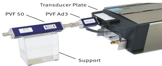
CCI PVKIT 1 Calibration Setup:
Calibration of Capacitive Coupling Clamp
IEC 61000-4-4 Standard Ed 3.0 recommends calibration of capacitive coupling clamps. EM TEST developed and designed the CCI PVKIT 1 calibration component according to the standard requirements.
Calibration requires the following facilities:
CCI PVKIT 1: with sensor board and support accessories
PVF 50: 50 ohm load resistance
PVF AD 3: 4 mm adapter for connecting the connection sensor board to the SHF coaxial connector of the KW 50
Calibration settings:
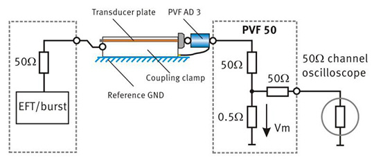
The sensor board should be placed in the capacitive coupling clamp with the end of the connection adapter aligned with the edge of the coupling board. Connect the connection adapter PVF AD 3 with a low-impedance connection strap to the ground reference plane of the 50 ohm coaxial measurement terminal/attenuator. Connect the load resistor KW 50 to the AD-CA EFT adapter. Use the acrylic support attachment to position the PVF 50 at the same height as the coupling clamp, 100 mm from the ground reference plane.
The distance between the sensor board and the PVF 50 measuring terminal/attenuator should be less than 0.1 m.
This technical data sheet gives a schematic diagram of the setup.
Calibration of the coupling clamp:
For calibration of the capacitive coupling plane, the open circuit voltage of the EFT/burst generator (50 ohm output) needs to be set to: 2,000 V
Resulting output voltage value across PVF 50 (50 ohm matching resistor): 1,000 V
Measuring voltage Vm: 10 V
Under 50 ohm input impedance, the voltage value measured by the oscilloscope: 5 V
Resulting attenuation (theoretical): 400:1
-
Specific indicators:
CCI capacitive coupling clamp
Maximum voltage
7.0 kV
Coupling plate size
140 mm x 1000 mm
high
Ground-coupling plate, 100 mm
connector
High pressure connector, coaxial
grounding
4 mm banana plug
DUT cable
Diameters up to 40 mm
weight
10.6 kg
general data
ambient temperature
10° C - 40° C
Relative humidity
85% max, non-condensing
atmospheric pressure
86 kPa - 106 kPa
ICC PVKIT 1 Calibration Kit
Sensor Board Technical Data
Description
Sensor board with 4mm connection plugSensor board with 4 mm connection plug
Acrylic support
Bracket for measurement adapter PVF50 at a level of 100 mm for capacitive coupling clamp calibration
PVF AD3
Adapter 4 mm to coaxial SHF connector
(to connect load resistor to sensor board)PVF BKIT 1 Burst Verification Kit
PVF 50
sensor board with 4mm connection plugCoaxial 50 Ohm Load Resistor for EFT/Burst Transient Verification
PVF 1000
Coaxial 1000 Ohm Load Resistor for EFT/Burst Transient Verification
PVF AD1
Adapter to match 4mm/6mm EUT output to PVF 50 load resistor, (connect load resistor to EUT output)