
Wisdom
-
-
-
-
EMC Test System For Civil Products
-
- Electrostatic Discharge Immunity
- Radiated, radio-frequency,electromagnetic field immunity
- Electrical Fast Transient Burst Immunity
- Surge immunity
- Immunity To Conducted Disturbance Induced by Radio Frequency Field
- Power Frequency Magnetic Field Immunity
- Voltage dips, short interruptions and voltage variations immunity
- Harmonics and interharmonics including mains signalling at AC power port, low frequency immunity
- Voltage Fluctuation Immunity Test
- Common mode disturbances in the frequency range 0 Hz to 150 kHz Immunity
- Ripple on DC input power port immunity
- Three-phase Voltage Unbalance Immunity Test
- Power Frequency Variation Immunity Test
- Oscillatory Wave Immunity Test
- Damped Oscillatory Magnetic Field Immunity Test
- Differential mode disturbances immunity test
- DC power input port voltage dip, short interruption and voltage variations test
-
Automotive Electronic EMC Test System
-
- Electrostatic Discharge Immunity
- Electrical Transient Conducted Immunity
- Immunity Test To Narrowband Radiated Electromagnetic Energy-Anechoic Chamber Method
- Immunity Test To Narrowband Radiated Electromagnetic Energy-Transverse Wave (TEM) Cell Method
- Immunity Test To Narrowband Radiated Electromagnetic Energy-large Current injection (BCI) method
- Immunity Test To Narrowband Radiated Electromagnetic Energy-Stripline Method
- Immunity Test To Narrowband Radiated Electromagnetic Energy-direct Injection Of Radio Frequency (RF) Power
- Immunity Test To Narrowband Radiated Electromagnetic Energy-Magnetic Field Immunity Method
- Immunity Test To Narrowband Radiated Electromagnetic Energy-Portable Transmitter Simulation Method
- Immunity Test To Narrowband Radiated Electromagnetic Energy-Conduction Immunity Method For Extended Audio Range
- High Voltage Electrical Performance ISO 21498-2 Test System
- High Voltage Transient Conducted Immunity (ISO 7637-4)
-
-
- CE101(25Hz ~ 10kHz power line conduction emission)
- CE102(10kHz ~ 10MHz power line conduction emission)
- CE106(10kHz ~ 40GHz antenna port conducted emission)
- CE107 (Power Line Spike (Time Domain) Conducted Emission)
- RE101(25Hz ~ 100kHz magnetic field radiation emission)
- RE102(10kHz ~ 18GHz electric field radiation emission)
- RE103(10kHz ~ 40GHz antenna harmonic and spurious output radiated emission)
-
- CS101(25Hz ~ 150kHz power line conduction sensitivity)
- CS102(25Hz ~ 50kHz ground wire conduction sensitivity)
- CS103(15kHz ~ 10GHz Antenna Port Intermodulation Conducted Sensitivity)
- CS104(25Hz ~ 20GHz antenna port unwanted signal suppression conduction sensitivity)
- CS105(25Hz ~ 20GHz antenna port intermodulation conduction sensitivity)
- CS106 (Power Line Spike Signal Conduction Sensitivity)
- CS109(50Hz ~ 100kHz shell current conduction sensitivity)
- CS112 (Electrostatic Discharge Sensitivity)
- CS114(4kHz ~ 400MHz cable bundle injection conduction sensitivity)
- CS115 (Conduction sensitivity of cable bundle injection pulse excitation)
- CS116(10kHz to 100MHz Cable and Power Line Damped Sinusoidal Transient Conduction Sensitivity)
- RS101(25Hz ~ 100kHz magnetic field radiation sensitivity)
- RS103(10kHz ~ 40GHz electric field radiation sensitivity)
- RS105 (Transient Electromagnetic Field Radiated Susceptibility)
-
-
-
-
-
-
-
-
-
-
EMC Test System For Civil Products
-
- Electrostatic Discharge Immunity
- Radiated, radio-frequency,electromagnetic field immunity
- Electrical Fast Transient Burst Immunity
- Surge immunity
- Immunity To Conducted Disturbance Induced by Radio Frequency Field
- Power Frequency Magnetic Field Immunity
- Voltage dips, short interruptions and voltage variations immunity
- Harmonics and interharmonics including mains signalling at AC power port, low frequency immunity
- Voltage Fluctuation Immunity Test
- Common mode disturbances in the frequency range 0 Hz to 150 kHz Immunity
- Ripple on DC input power port immunity
- Three-phase Voltage Unbalance Immunity Test
- Power Frequency Variation Immunity Test
- Oscillatory Wave Immunity Test
- Damped Oscillatory Magnetic Field Immunity Test
- Differential mode disturbances immunity test
- DC power input port voltage dip, short interruption and voltage variations test
-
Automotive Electronic EMC Test System
-
- Electrostatic Discharge Immunity
- Electrical Transient Conducted Immunity
- Immunity Test To Narrowband Radiated Electromagnetic Energy-Anechoic Chamber Method
- Immunity Test To Narrowband Radiated Electromagnetic Energy-Transverse Wave (TEM) Cell Method
- Immunity Test To Narrowband Radiated Electromagnetic Energy-large Current injection (BCI) method
- Immunity Test To Narrowband Radiated Electromagnetic Energy-Stripline Method
- Immunity Test To Narrowband Radiated Electromagnetic Energy-direct Injection Of Radio Frequency (RF) Power
- Immunity Test To Narrowband Radiated Electromagnetic Energy-Magnetic Field Immunity Method
- Immunity Test To Narrowband Radiated Electromagnetic Energy-Portable Transmitter Simulation Method
- Immunity Test To Narrowband Radiated Electromagnetic Energy-Conduction Immunity Method For Extended Audio Range
- High Voltage Electrical Performance ISO 21498-2 Test System
- High Voltage Transient Conducted Immunity (ISO 7637-4)
-
-
- CE101(25Hz ~ 10kHz power line conduction emission)
- CE102(10kHz ~ 10MHz power line conduction emission)
- CE106(10kHz ~ 40GHz antenna port conducted emission)
- CE107 (Power Line Spike (Time Domain) Conducted Emission)
- RE101(25Hz ~ 100kHz magnetic field radiation emission)
- RE102(10kHz ~ 18GHz electric field radiation emission)
- RE103(10kHz ~ 40GHz antenna harmonic and spurious output radiated emission)
-
- CS101(25Hz ~ 150kHz power line conduction sensitivity)
- CS102(25Hz ~ 50kHz ground wire conduction sensitivity)
- CS103(15kHz ~ 10GHz Antenna Port Intermodulation Conducted Sensitivity)
- CS104(25Hz ~ 20GHz antenna port unwanted signal suppression conduction sensitivity)
- CS105(25Hz ~ 20GHz antenna port intermodulation conduction sensitivity)
- CS106 (Power Line Spike Signal Conduction Sensitivity)
- CS109(50Hz ~ 100kHz shell current conduction sensitivity)
- CS112 (Electrostatic Discharge Sensitivity)
- CS114(4kHz ~ 400MHz cable bundle injection conduction sensitivity)
- CS115 (Conduction sensitivity of cable bundle injection pulse excitation)
- CS116(10kHz to 100MHz Cable and Power Line Damped Sinusoidal Transient Conduction Sensitivity)
- RS101(25Hz ~ 100kHz magnetic field radiation sensitivity)
- RS103(10kHz ~ 40GHz electric field radiation sensitivity)
- RS105 (Transient Electromagnetic Field Radiated Susceptibility)
-
-
-
-
-
-
Product
EMC Testing Solution Provider
CA PFS Power Fault Simulator Verification Component
Brand:
EM TEST

- Product Description
- Main features
- Technical parameters
-
- Commodity name: CA PFS Power Fault Simulator Verification Component
- Commodity ID: 1064617265925345280
- 品牌11: EMTEST
- 行业: 民用
- 描述: The inrush current of the power failure simulator according to EN/IEC 61000-4-11 standard can be verified by the CA PFS circuit box.
- 品牌: EM TEST
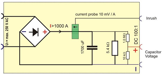
CA PFS - Measuring Inrush Current for Power Failure Simulators
The inrush current of a power failure simulator according to EN/IEC 61000-4-11 can be verified with the CA PFS circuit box. Annex A.3 of the EN/IEC 61000-4-11 standard makes specific requirements for its circuit. The built-in current provides a 10mV/A voltage signal at the corresponding BNC output terminal connected to the oscilloscope, and the inrush current is measured through the selected 1M ohm input resistance.
-
main feature:
Combined Calibration Kit
Conforms to EN/IEC 61000-4-11 standard
Built-in 10mV/A current probe
Built-in 3.3kohm resistor for energy storage capacitor discharge
The monitoring output is used to measure the residual capacitor voltage (voltage division ratio 100:1)
Standards compliant:
IN 61000-4-11
IN 61000-4-34
IEC 61000-4-11
IEC 61000-4-34
Application overview:
Based on the power fault generator specified in EN/IEC61000-4-11, the generator needs to withstand the surge current higher than 500A@220-240VAC and 1000A@250-600VAC.
EN/IEC 61000-4-34 stipulates the minimum surge current and rated equipment current of 500 A and above or even more than 1000A.
Power supplies are usually not capable of delivering such high inrush currents. The true current supply from the mains is limited by the supply system impedance and is expected to be around 100 A to 200 A. The following guidelines are recommended to be followed in order to properly verify the surge current generator for a mains fault:
A peak current capacitor of about 20 uF or more is installed in parallel with the mains. This capacitor will provide the peak inrush current generator into the CA PFS through a power failure. Due to the high inrush current and mains fuse test duration is limited to a few milliseconds. The maximum duration td depends on the current capacity of the overcurrent protective device installed in the mains. When testing, the power failure generator must be set to dU mode with only one PFS input (PF1 or PF2) connected to the power supply. Measure the inrush current with a digital memory connected to the BNC output.
Oscilloscope input impedance = 1 M ohm
500A=5V peak signal
The built-in storage capacitor (1700 uF capacitor) only needs to be discharged to a few volts before the next inrush current measurement. This residual voltage can be output with a voltmeter at the capacitor voltage (divider ratio 100:1).
-
Specific indicators:
Capacitor voltage output
scope
100:1
Accuracy
± 10 %
Connector
4 mm safety lab connector
Impedance range
1 M ohm
Current monitor output
scope
10 mV/A
Accuracy
± 5%
Connector
BNC
Impedance range
1 M ohm recommended
general data
line voltage
100 V - 250 V max.
electric shock
1,000 A
capacitance
1,700 uF +/-20%
Discharge resistance
5,400 ohm +/-10%
size
36cm x 20cm x 15cm (LxWxH)
weight
about 3.5 kg
temperature
10 °C to 35 °C
Relative humidity
25 % - 75 %, non-condensing
atmospheric pressure
86 kPa - 106 kPa