
Wisdom
-
-
-
-
EMC Test System For Civil Products
-
- Electrostatic Discharge Immunity
- Radiated, radio-frequency,electromagnetic field immunity
- Electrical Fast Transient Burst Immunity
- Surge immunity
- Immunity To Conducted Disturbance Induced by Radio Frequency Field
- Power Frequency Magnetic Field Immunity
- Voltage dips, short interruptions and voltage variations immunity
- Harmonics and interharmonics including mains signalling at AC power port, low frequency immunity
- Voltage Fluctuation Immunity Test
- Common mode disturbances in the frequency range 0 Hz to 150 kHz Immunity
- Ripple on DC input power port immunity
- Three-phase Voltage Unbalance Immunity Test
- Power Frequency Variation Immunity Test
- Oscillatory Wave Immunity Test
- Damped Oscillatory Magnetic Field Immunity Test
- Differential mode disturbances immunity test
- DC power input port voltage dip, short interruption and voltage variations test
-
Automotive Electronic EMC Test System
-
- Electrostatic Discharge Immunity
- Electrical Transient Conducted Immunity
- Immunity Test To Narrowband Radiated Electromagnetic Energy-Anechoic Chamber Method
- Immunity Test To Narrowband Radiated Electromagnetic Energy-Transverse Wave (TEM) Cell Method
- Immunity Test To Narrowband Radiated Electromagnetic Energy-large Current injection (BCI) method
- Immunity Test To Narrowband Radiated Electromagnetic Energy-Stripline Method
- Immunity Test To Narrowband Radiated Electromagnetic Energy-direct Injection Of Radio Frequency (RF) Power
- Immunity Test To Narrowband Radiated Electromagnetic Energy-Magnetic Field Immunity Method
- Immunity Test To Narrowband Radiated Electromagnetic Energy-Portable Transmitter Simulation Method
- Immunity Test To Narrowband Radiated Electromagnetic Energy-Conduction Immunity Method For Extended Audio Range
- High Voltage Electrical Performance ISO 21498-2 Test System
- High Voltage Transient Conducted Immunity (ISO 7637-4)
-
-
- CE101(25Hz ~ 10kHz power line conduction emission)
- CE102(10kHz ~ 10MHz power line conduction emission)
- CE106(10kHz ~ 40GHz antenna port conducted emission)
- CE107 (Power Line Spike (Time Domain) Conducted Emission)
- RE101(25Hz ~ 100kHz magnetic field radiation emission)
- RE102(10kHz ~ 18GHz electric field radiation emission)
- RE103(10kHz ~ 40GHz antenna harmonic and spurious output radiated emission)
-
- CS101(25Hz ~ 150kHz power line conduction sensitivity)
- CS102(25Hz ~ 50kHz ground wire conduction sensitivity)
- CS103(15kHz ~ 10GHz Antenna Port Intermodulation Conducted Sensitivity)
- CS104(25Hz ~ 20GHz antenna port unwanted signal suppression conduction sensitivity)
- CS105(25Hz ~ 20GHz antenna port intermodulation conduction sensitivity)
- CS106 (Power Line Spike Signal Conduction Sensitivity)
- CS109(50Hz ~ 100kHz shell current conduction sensitivity)
- CS112 (Electrostatic Discharge Sensitivity)
- CS114(4kHz ~ 400MHz cable bundle injection conduction sensitivity)
- CS115 (Conduction sensitivity of cable bundle injection pulse excitation)
- CS116(10kHz to 100MHz Cable and Power Line Damped Sinusoidal Transient Conduction Sensitivity)
- RS101(25Hz ~ 100kHz magnetic field radiation sensitivity)
- RS103(10kHz ~ 40GHz electric field radiation sensitivity)
- RS105 (Transient Electromagnetic Field Radiated Susceptibility)
-
-
-
-
-
-
-
-
-
-
EMC Test System For Civil Products
-
- Electrostatic Discharge Immunity
- Radiated, radio-frequency,electromagnetic field immunity
- Electrical Fast Transient Burst Immunity
- Surge immunity
- Immunity To Conducted Disturbance Induced by Radio Frequency Field
- Power Frequency Magnetic Field Immunity
- Voltage dips, short interruptions and voltage variations immunity
- Harmonics and interharmonics including mains signalling at AC power port, low frequency immunity
- Voltage Fluctuation Immunity Test
- Common mode disturbances in the frequency range 0 Hz to 150 kHz Immunity
- Ripple on DC input power port immunity
- Three-phase Voltage Unbalance Immunity Test
- Power Frequency Variation Immunity Test
- Oscillatory Wave Immunity Test
- Damped Oscillatory Magnetic Field Immunity Test
- Differential mode disturbances immunity test
- DC power input port voltage dip, short interruption and voltage variations test
-
Automotive Electronic EMC Test System
-
- Electrostatic Discharge Immunity
- Electrical Transient Conducted Immunity
- Immunity Test To Narrowband Radiated Electromagnetic Energy-Anechoic Chamber Method
- Immunity Test To Narrowband Radiated Electromagnetic Energy-Transverse Wave (TEM) Cell Method
- Immunity Test To Narrowband Radiated Electromagnetic Energy-large Current injection (BCI) method
- Immunity Test To Narrowband Radiated Electromagnetic Energy-Stripline Method
- Immunity Test To Narrowband Radiated Electromagnetic Energy-direct Injection Of Radio Frequency (RF) Power
- Immunity Test To Narrowband Radiated Electromagnetic Energy-Magnetic Field Immunity Method
- Immunity Test To Narrowband Radiated Electromagnetic Energy-Portable Transmitter Simulation Method
- Immunity Test To Narrowband Radiated Electromagnetic Energy-Conduction Immunity Method For Extended Audio Range
- High Voltage Electrical Performance ISO 21498-2 Test System
- High Voltage Transient Conducted Immunity (ISO 7637-4)
-
-
- CE101(25Hz ~ 10kHz power line conduction emission)
- CE102(10kHz ~ 10MHz power line conduction emission)
- CE106(10kHz ~ 40GHz antenna port conducted emission)
- CE107 (Power Line Spike (Time Domain) Conducted Emission)
- RE101(25Hz ~ 100kHz magnetic field radiation emission)
- RE102(10kHz ~ 18GHz electric field radiation emission)
- RE103(10kHz ~ 40GHz antenna harmonic and spurious output radiated emission)
-
- CS101(25Hz ~ 150kHz power line conduction sensitivity)
- CS102(25Hz ~ 50kHz ground wire conduction sensitivity)
- CS103(15kHz ~ 10GHz Antenna Port Intermodulation Conducted Sensitivity)
- CS104(25Hz ~ 20GHz antenna port unwanted signal suppression conduction sensitivity)
- CS105(25Hz ~ 20GHz antenna port intermodulation conduction sensitivity)
- CS106 (Power Line Spike Signal Conduction Sensitivity)
- CS109(50Hz ~ 100kHz shell current conduction sensitivity)
- CS112 (Electrostatic Discharge Sensitivity)
- CS114(4kHz ~ 400MHz cable bundle injection conduction sensitivity)
- CS115 (Conduction sensitivity of cable bundle injection pulse excitation)
- CS116(10kHz to 100MHz Cable and Power Line Damped Sinusoidal Transient Conduction Sensitivity)
- RS101(25Hz ~ 100kHz magnetic field radiation sensitivity)
- RS103(10kHz ~ 40GHz electric field radiation sensitivity)
- RS105 (Transient Electromagnetic Field Radiated Susceptibility)
-
-
-
-
-
-
Product
EMC Testing Solution Provider
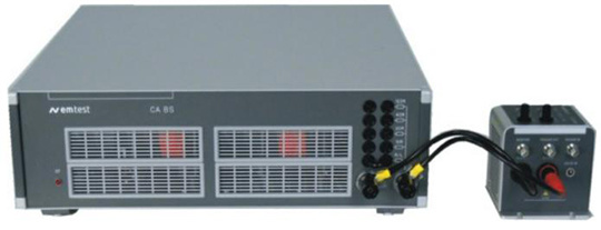
Load Impedance for CA BS 200N, BS200NX Electronic Switches
Brand:
EM TEST

- Product Description
- Main features
- Technical parameters
-
- Commodity name: Load Impedance for CA BS 200N, BS200NX Electronic Switches
- Commodity ID: 1064612400608202752
- 品牌11: EMTEST
- 行业: 汽车电子和整车
- 描述: The performance of BS 200N series semiconductor switches can be verified between 0.6ohm and 50uH in series.
- 品牌: EM TEST
The performance of BS 200N series semiconductor switches can be verified between 0.6ohm and 50uH in series. CA BS 200N is directly connected to the output terminal of BS 200N series, and the switching parameters of BS 200N series are measured through the size of the connected load.
In addition, CA BS 200N has a set of shunt resistors with resistances of 10ohm, 20ohm, 40ohm and 120ohm, which are tested according to different standards of ISO7637-2:2011 and ISO7637-2:2004.
-
main feature:
Verified between 0.6ohm in series with 50uH according to ISO7637-2:2004 standard
DC voltage up to 28V
Maximum load current 50A
Built-in shunt resistors for emission testing, the resistances are 10ohm, 20ohm, 40ohm and 120ohm
Overheating protection
Standards compliant:
ISO 7637-1:1990
ISO 7637-2:2004
ISO 7637-2:2011
Test build:
According to the standard requirements of ISO7637-2, the BS 200N series requires a rise/fall time standard of 300ns +/-20% between 0.6ohm and 50uH in series. CA BS200N is directly connected to BS200N series through short leads to verify its switching characteristics. Also, connect a parameter with enough bandwidth to put in the oscilloscope to display the rise/fall times.
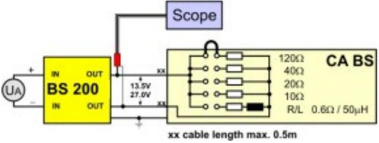
Cable installation:
In order to accurately verify the rise/fall time characteristics of the BS200N switch series, the connecting cables should be as short as possible. It is recommended that the longest connection between the load impedance of CA BS 200N and the BS200N series switch is 0.5 meters (as shown on the right)
-
Specific indicators:
Specification
Maximum battery supply voltage
28V DC
load current
Max 50A
operating time
About 1 hour when powered by 13.5V, about 10 minutes when powered by 28V
overheating light
LED
Protect
shutdown (overheat sensor)
cool down
Forced air cooling
Technical data
load
0.6ohm in series with 50uH
parallel resistive shunt
10ohm, 20ohm, 40ohm and 120ohm, choose according to the shorting connector
general data
size
19''/3HU, 133×500×500mm
weight
About 19.1kg
powered by
80V-240V AC
fuse
1A slow blow fuse